Concrete Strength Testing
Infrastruct provides our Clients with a wide range of practical solutions for both Intrusive and Non-Destructive (NDT/NDE) evaluation of concrete strength on many types of structures including motorway and road bridges, single and multi-storey buildings, tunnels, dams, drinking water reservoirs and concrete tanks.
An evaluation of the compressive strength of hardened concrete is frequently required in the construction industry. There are many reasons to assess the compressive strength of concrete including:
- A requirement by the designers to verify the compressive strength in an existing structure that will be structurally modified, redesigned for other uses or where the structure was damaged i.e. fire.
- A requirement to check the structural adequacy in the case of a non-conformity of the standard cube test (or when cube results are not available to the designers.
- In the case of a dispute over concrete quality or defective workmanship in new construction works.
The main Standard providing information on the approaches to be adopted as part of an evaluation is I.S. ‘Assessment of in-situ compressive strength in structures and pre-cast concrete components’.
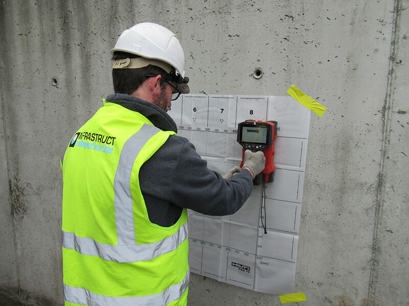
I.S. EN 13791:2007 provides guidance on direct (cores) and indirect (Rebound Hammer, Ultrasonic Pulse Velocity and Pull-out Force) methods for assessing the in-situ compressive strength of hardened concrete.
At Infrastruct, we provide the following testing to assess compressive strength of hardened concrete:
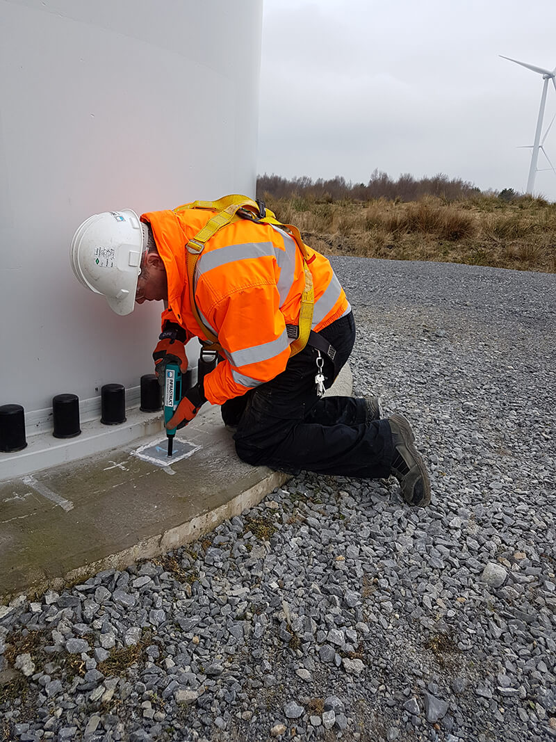
- Diamond coring of the concrete elements and structures – Core diameters: 50mm, 75mm, 100mm, 150mm
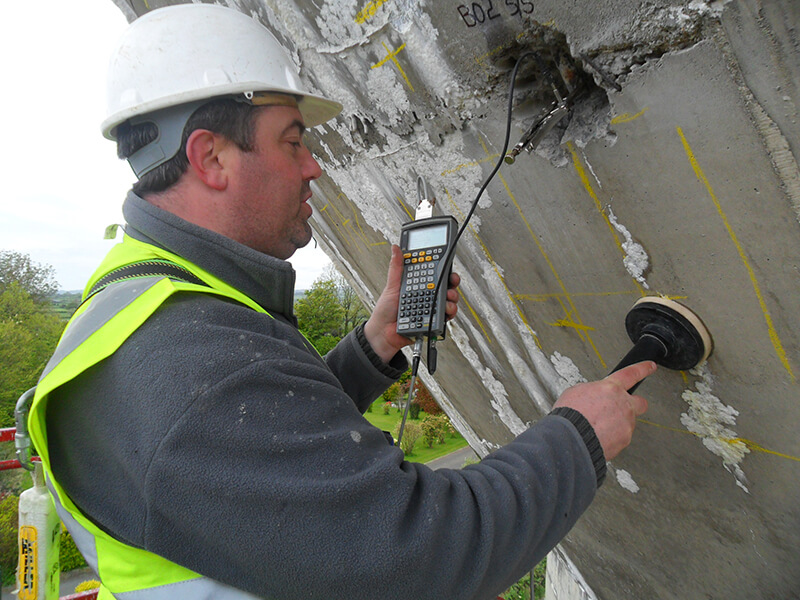
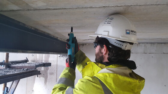
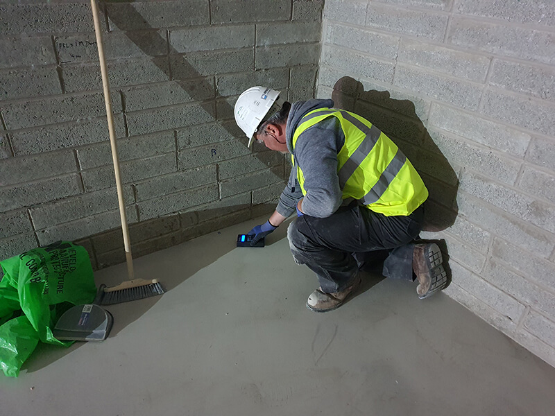
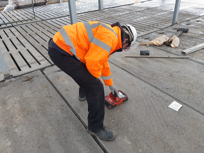
- Rebound Hammer testing (normal and early age concrete testing)
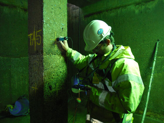
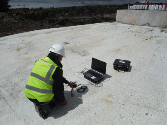
- Ultrasonic Pulse Velocity (UPV) testing
- SonReb testing and analysis
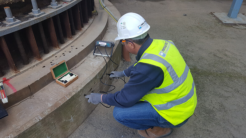
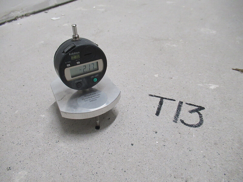
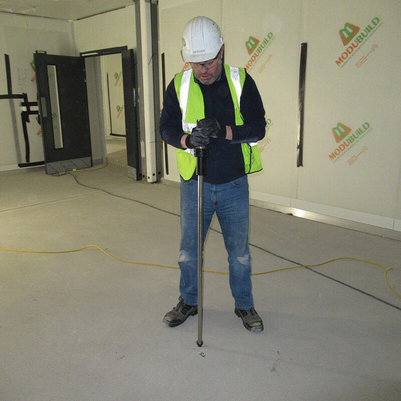
- Capo and Lok testing


Test results and related information is provided in a detailed report with interpretation and AutoCAD drawings.
Also, as part of our Services, we can work with our Clients to monitor strength development in early age concrete structures using the Maturity method (ASTM C1074). This is a non-destructive testing approach that allows us to estimate the early-age and compressive strength of in-place concrete in real-time. The technique is based on the principle that concrete strength is directly related to its hydration temperature history.
For more information on this or any construction-related testing, please contact us.